How
to build a Babington Oil Burner
last update
2007-09-15
So you want to make a Babington
burner?

(click
for high-resolution image)
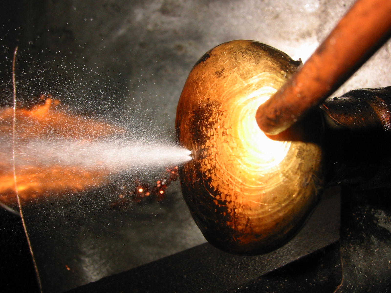
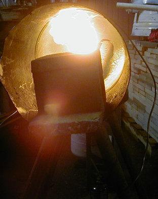
Image is of a dual .0135"
Babington atomizer burning kerosene. Liquid fuel is delivered
through the 1/4" copper pipe at right, atomized by the two holes
blowing 30 PSI compressed air, and a flame is sustained on the left
side as long as the fuel flows. The excess fuel that pours over
the knob is caught by a steel funnel (in background) that guides it
into a sump.
Index
Overview
History
Fuels
burned
Making a Babington
Burner
Babington
Atomizer (the "nozzle")
Drilling
the Itty Bitty Hole
Compressed
Air/Pressurized Gas
Fuel
Supply
Burner
Tube
Fuel
Sump
Starting your
Babington
Pre-heating
the Oil
Adjust
the Compressed Air/Gas Flow
Constant
Fuel Flow
Constant
Air Flow
Additional
Information
Acknowledgements
The
(currently anemic) Babington Oil Burner FAQ is available
here.
Overview
A
Babington burner works like a whale's blow hole. Fuel flowing
over a curved creates a thin film due to surface tension. When
this film is pierce by a jet of air from a very small hole (typically
.010 inch), the fuel is not only atomized quite well, but also,
enough air is entrained by the atomized fuel to complete the
combustion, so there's no need for additional forced air for
combustion.
The huge advantage of Babington burners is that
there's no nozzle to clog: the fuel flows over the small air
hole, rather than through it, making this a very popular waste oil
burner. So long as the fuel pump can handle whatever is in the
liquid, be it metal shavings, french fry bits, or dirt, the burner
will continue working without fail. The tradeoff for this lack
of clogging is that you need to have a fuel sump that's located below
the atomizer nozzle.
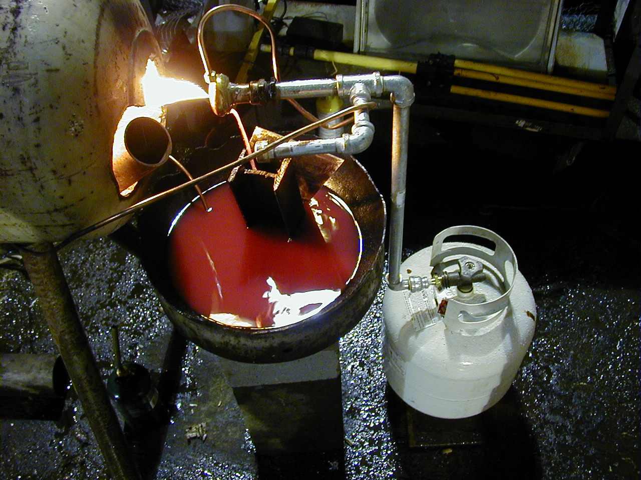
Here's a picture of my very first
Babington - not very elegant, but it worked!

The
parts as seen are:
1) a Babington atomizer (the doorknob, in this
case). Normally, this is actually inside the burner tube, but I
pulled it out for demostration purposes.
2) source of compressed
air or gas (the 20lb propane container)
3) liquid fuel pump
(typically a gear oil pump) (not visible, but hooked to the copper
tubing)
4) burner tube (the old 100lb propane tank with the end
cut off). I mounted this on four legs to made a hand-height
hand warmer for an outdoor work area, and it worked great!
5) fuel
sump of some sort to catch the unburned fuel that runs over the
atomizer (the cut-off end of the old 100 lb propane tank)
6)
splash guard - part played by that chunk of H-beam, otherwise fuel
splashes everywhere.
Here's an end view of the Babington while
running (looking up cut-out propane tank):
(click
for higher resolution image)
That's a cinderblock just
downstream of the burner that greatly assisted in keeping the flame
running. Also, note that there's no smoke! When
everything is running properly, there's just wavy hot air as
exhaust.
You can also kind of see the gear oil pump
floating in midair beneath the burner tube It's drawing fuel
from the upper left hand corner of the sump, pumping it around the
propane tank twice (to preheat the fuel), and then pouring it over
the doorknob where the fuel gets atomized.
Things odd about
this setup include:
1) there's no propane regulator, and the
propane flow was difficult to control just using the tank knob
2)
I was making a dual-fuel burner (kerosene/glycerol), hence the "T"
in the galvanized propane tubing and one capped end.
Someday...
3) since this was a test setup, there's no fuel tank -
I just filled up the sump and ran off that fuel
History
Patent
# 3,425,058
was granted to Robert S. Babington in 1969. It has expired, and
the burner design is now in the public domain.
Patent #
4,155,700
was granted to Robert S. Babington in 1979. It details a
dual-atomizer Babington burner that uses forced air for combustion.
It looks exactly like Babington
Technology's Airtronics(r) burner (fancy that), which was
primarily marketed for military food preparation and runs off of
diesel fuel. This patent has also expired.
John
Archibald has really picked up where Mr. Babington left off, and is
the father of the home-built Babington. He has written at length
about the Babington in the Wastewatts group over the past few years,
so if you're going to read the archives from just one person, he's
the one.
Fuels
Due
to the excellent atomization, Babington burners will burn many heavy
and waste oils such as:
diesel (~140,000 BTU/gallon)
biodiesel (~130,000 BTU/gallon)
kerosene (~140,000 BTU/gallon)
waste transmission / motor oil
(~150,000 BTU/gallon)
waste vegetable oil (WVO) (~130,000 BTU/gallon)
(all the BTU values seem to change +/- 5% based on source and quality
- take these numbers for comparison purposes only)
The only
difference is that the preheat temperature, and compressed gas PSI,
will change for optimum burning of different fuels.
I estimate
that a single .010" hole consumes about 1/3 gallon of liquid
fuel per hour. This works out to about an 40,000 BTU heater
with WVO. To increase the output of the burner, drill another
hole 1/4" from the original hole and you will double your fuel
usage & heat output. (If the hole is closer than 1/4",
the streams will overlap and it won't burn quite as well)
Warning:
do not attempt to burn gasoline, methanol, or an other
volatile fuel with a Babington burner! The whole sump as well
as the atomizer can catch fire explosively, and while that can be
exciting, that's not not the goal here. :) I once burned some
biodiesel that still had some methanol left in it, and yes, it was
quite exciting, so I'm speaking from experience here.
Making
a Babington Burner
Making
a Babington Burner is faily simple, but there are a number of pieces
that have to work together in order to do so.
Also, please
note that I'm not a mechanical engineer (I'm a software engineer,
actually), and playing with combustible fuels, while fun, can be
rather dangerous. I highly recommend keeping a fire
extinguisher close to your Babington burner at all times, especially
while you're tinkering with it.
Babington Atomizer
(the "nozzle")
The fuel needs to flow over a
curved surface in order to work properly.
Complete
Babington nozzles can be purchased from Andy Mahoney at Homebrew
Power, but what's the fun in that?
The professional-looking DIY method is to just buy a hollow steel
ball. Any size ball, made of any common metal, in any
reasonable diameter is available from
J. G. Braun Co. • 8145
River Drive • Morton Grove, IL 60053053-2645
800-323-4072 •
847-663-9300 • Fax: 847-663-0667 • info@jgbraun.com
A 3"
hollow steel ball is about $10.50 (but with $75 minimum order) from
RB
Wagner
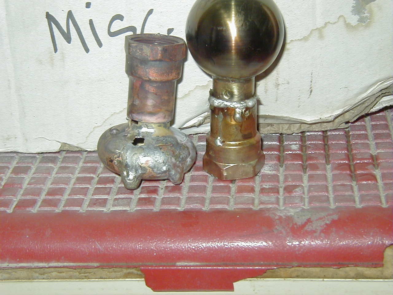
However, some (most?) people use keyless interior
doorknobs. Cut off the shaft of a knob with a sabre saw, then
braze or JB Weld a copper SLIP x FPT adapter onto the shaft,
and screw into your compressed gas source. Make sure you clean
both surfaces with a solvent first, and rough up the surfaces with a
wire brush/wheel or sandpaper. I have had some luck in this
department, but a couple of failed attempts, too:

(click
for larger picture)
I tried to braze both of them, but the
doorknob on the left just wouldn't seal (it was actually a pro I
asked to help me that blew a hole through it!). The knob on the
right was purchased new, but I couldn't get anything to adhere to,
even after thoroughly roughing up the surface with a wire brush
wheel. A very old doorknob from a salvage yard, probably made
pure brass, worked just fine, though.
Alternately, several
folks have successfully used brass end caps with a groove cut into
them.
What size atomizer is right for you? Dave Brown
says:
"I have tried both large and small balls.
The large balls were door knobs (interior, keyless, lockless) drilled
with 0.010" holes (one hole and two holes). The small
balls were brass end caps (flare fittings) with 0.0135" hole
(one only), with and without the groove.
I don't think it's as
simple as comparing ball sizes, as other factors such as dirt in the
fuel and delivery system play as big a roll.
The overriding
goal or principle, regardless of size, is that optimum atomization of
the oil requires a thin film of oil over the ball at the point where
the pressurized air exits the ball. So, given that basic
premise, my observations are as follows:
BIG BALLS: If
your method of delivering the oil to the ball isn't precise, then the
large ball has a decided advantage in that it will accommodate a
higher flow rate and still deliver a thin film of oil to the air
stream. Excess oil runs off and is simply drained to the
sump/oil tank and recirculated. Since this oil has been
pre-heated, it warms and lowers the viscosity of the oil in the sump.
There is more latitude in fuel flow rates while continuing to deliver
the desired thin film of oil to the air stream. Seeing as
consistent fuel delivery seems to be a constant headache, at least
according to the history of posts to this list, the large ball is
more forgiving. It seems to me that it tolerates fluctuations
in fuel flow rather well. Last, but not least, is that the
larger openings in the fuel flow controls will tolerate dirtier oil
and larger particle size of contaminates. In other words
the fuel lines and valves won't clog as easy. The need to have
fairly well filtered waste oil or drawing well away from sediment is
moot.
LITTLE BALLS: They sure do work just fine and
deliver the oil to the air stream as required. But they are
different from the big balls. I used brass end caps (3/4"
and 5/8" size). They come with a flat end which makes
locating the center and drilling easier (to an extent). I then
chucked mine into a drill press and while they spun I used an angle
grinder then some fine sand paper to round off the flat area. I
found out that you must
be careful because the caps aren't as
thick as you think they are. It's easy to take too much metal
off and ruin the ball. Now, given the size of the ball I found
that you have to control your fuel delivery much more. It is
easy to flood and overpower the air stream. Even a little bit
of excess flooding can result in a deterioration of droplet size in
the fuel fog, which in turn affects combustion. I found that
you really have to control the fuel delivery to the point of very
little runoff or no runoff at all. This has it's own set of
plusses and minuses. If you can get manage to achieve zero
runoff then the plumbing for the runoff return line is taken away.
But, you should probably have it plumbed for runoff anyway so you
don't create a puddle of overflow in the burner. Since you are
targeting such narrow control over the fuel delivery (i.e. needle
valves or
similar) you have to be concerned with particulates in
the fuel that could easily build up in the valve and create a
blockage. So, here again I've concluded that the fuel delivery
method and level of filtration is the primary determining factor as
to which size ball you really need."
Drilling
the Itty Bitty Hole
For the
atomizer to work properly, the hole for the compressed gas flow needs
to be very, very small. .010" is recommended, though you
can use .0135" or even up to .0200". Any bigger than
that, and the droplet size gets too big, and results in poor
atomization.
Q: where do I get .010 drill bits?
A: What you
want are re-sharpened drill bits that are out of spec (too short)
from the drilling of circuit boards. They are solid carbide with 1/8"
shanks.
A source for small quantities of resharpened bits is
Drill Bit City
5 packs of .0135" bits: $5.75
5 pack of
.0100" bits: $7.15
These bits are so small that if you
look at them sideways, they'll break. Ever break a 1/16"
drill bit? These bits are less than 3% the size of a 1/16"
bit. Using a high speed micro drill (like a Dremel tool) is
highly recommended. Also, Dremel drill presses are inexpensive
(about $40),
and make it easy to drill the hole. Just make sure you clamp
your piece down tightly, and drill very, very slowly. I've
heard that it's possible to drill the hole freehand if you're going
through a very thin-wall doorknob, but I broke several bits trying
this, and don't recommend it.
To double the heat output, just
drill two holes about 1/4" apart. Note that in my image
above of the dual .0135 hole Babington atomizer, the holes are too
closely placed - they should be about 1/4" apart instead of the
1/16" apart as shown. The two fuel sprays collide and form
larger droplets, which isn't ideal, but still works.
Compressed
Air/Pressurized Gas
Using compressed air for
atomization is cheap, and works great. Highly recommended.
From this orifice air flow chart,
we can estimate that a single .010 hole Babington should use
approximately 4 cubic feet/hour at 30 PSI (a .010 hole should about
40% the air that a 1/64 hole uses).
Since
the air needed is quite low, someone on Wastewatts recommended "some
refrigeration compressors, even possibly an aquarium air
pump."
Possible sources for suplus (read: cheap) air
compressors:
www.surpluscenter.com
http://surpluscityliquidators.com/
If
you don't have an air compressor handy, propane works fine, too.
Expect to use about 0.1 gallons of propane/hour of runtime for each
.0135 hole that you drill. Since 0.1 gallons of propane =
4000 BTU, and a one hole Babington uses about 2/3 gallon of fuel per
hour (~80k BTU), the propane component of the heating is less than 5%
of the total heating mixture.
Propane pressure seems to make
the mixture a little rich, and you have to care about propane leaks,
which is annoying.
Fuel Supply
Fuel
Pump: A gear oil pump is highly recommended. Again, try the
following places for cheap surplus oil and fuel
pumps:
www.surpluscenter.com
http://surpluscityliquidators.com/
I
got a 12V gear oil pump that worked great for $20 from Surplus
Center.
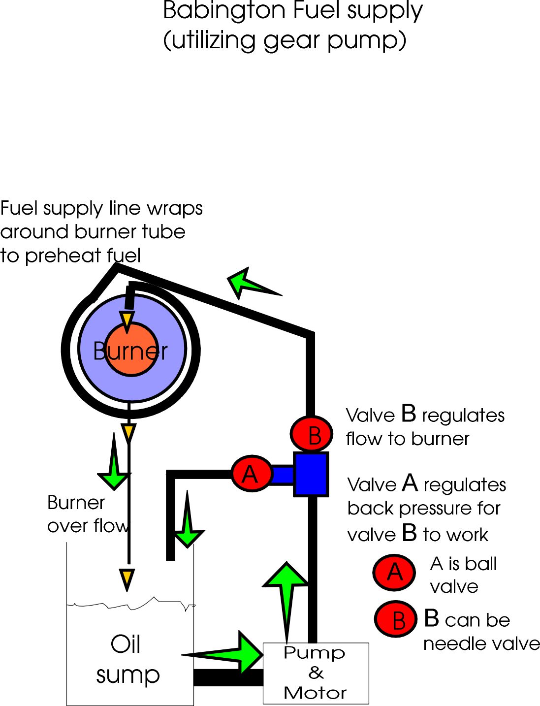
Dave Brown made a nice diagram of how the fuel supply
pump is hooked up in the system:
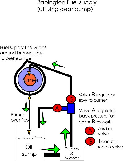
(click
for larger image)
Gravity Feed: Generally, this is a
bit more difficult because as the liquid level in the source
container drops, the fuel pressure drops, and hence the fuel flow
over the atomizer changes. Some people have gotten it to work
just fine, but using a fuel pump is easier.
Constant Head
System: Whether you're having problems with an oil pump that
pumps at too high of a pressure, or a inconsistent fuel pressure due
to gravity feed, one option to guarantee constant fuel flow is to use
a constant head system like this one designed by John
Archibald:
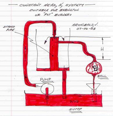
I
think this is one of the most elegant plumbing systems. So long
as the volume of fuel delivered by the pump is sufficient for the
burner, it doesn't matter what kind of pump you have, how much fuel
it's delivering, or the delivered fuel pressure. This will
convert it into a low volume, low pressure delivery system, which is
what you want in this case (high pressure will splatter fuel off the
atomizing ball).
Regardless of how you achieve it, a constant
fuel flow is necessary. If the flow varies at all, the flame
can start oscillating and put itself out.
Burner
Tube
John Archibald recommends
a 6" x 3' tube. Personally, I've had pretty good luck with
a 3" ID by 3' long pipe so long as it is a single
hole.010" atomizer. Heavy wall pipe is better, as it holds
more heat in, making for better combustion.
I've also managed
to get a dual hole atomizer working with an old 12" diameter
propane tank (see above pictures). However, when you use a
larger diameter pipe, the flame tends to be unstable once the burner
tube heats up. After watching it go out a few dozen times, my
theory is that the fuel & air mixture expands so much that it
creates a pressurized section in the pipe that is strong enough to
overcome the air jet coming out of the Babington nozzle, and this
leads to a burner oscillation that will put the flame out. It's
a distictive sound that you'll get to know well until you get it
fixed. How I overcame this problem with the large diameter pipe
was to install an inner combustion pipe, 3" x 12", to
channel the flame and assist in air entrainment.
You should
also block off most of the back of the burner tube, ideally with an
adjustable flue of some sort. I just stuck a cinderblock
downstream in the pipe (visible in the pictures above) Iit
retards the airflow away from the atomizer, reducing the chance of it
blowing out, as well as helping it to stay hot. It was
also quite necessary when running in a windy location.
Also,
drilling four holes in the burner tube can be quite helpful.
Dave Brown says:
"These holes need to be placed in
opposing pairs. One pair left and right on the pipe and
just slightly (i.e. about 1" plus or minus) forward of the front
tip of the nozzle/ball. The next set should be top and bottom
on the pipe and just slightly (i.e. about 1" plus or minus)
forward of the first set of holes. This does more than simply
admit combustion air. It disturbs the shape of the fuel
cone and improves the air/fuel mix in the process, thus improving
combustion efficiency and propagation. More holes may help, but
if there are too many or admit too much air at low velocity then it
does little to help combustion. Also, too much air means that
you have to also heat that air and send it up the chimney rather than
into the walls of the pipe and hence into the space to be heated ...
your "shop", as it were. I do not know if there is
any information available regarding how much air or hole area is
best. In my case, using a 6" diameter pipe, I drilled 3/8"
(9.5mm) diameter holes and they seem to do the job just fine."
Fuel
Sump
This catches the fuel that
runs over the atomizer, but is not atomized. I used the bottom
part of an old 20 lb propane cannister as my sump, and used a piece
of sheet metal rolled into a cone to keep the fuel from splashing
into the sump (this was an improvement from the small H-beam in the
photo above). I should have made the sump deeper than the 3
inches it is: the next version will be an old 20 lb propane tank with
the top cut off, which should hold about 12" deep and hold 3
gallons. This will be my primary fuel source, and when burning
1 gallon per hour, will act as a 3-hour timer on the burner - just
about right for my purposes (YMMV).
Starting
Your Babington Burner (and how to keep the flame from going
out)
Turn on the gear oil pump, turn on the air
compressor, and then light the atomized liquid fuel with a small
propane torch or butane jet lighter. Watch it burn for a second
or two and then, most likely, go out. This begs the question:
how do you keep it lit?
Pre-heating the
Oil
Pre-heating the oil before it pours over the
atomizer is pretty much required to keep your Babington lit.
The simplest way to do this is just make a couple of wraps around
your burner tube with 1/4" copper tubing before delivering the
fuel to the gear oil pump. Adjust the number of wraps until the
fuel is preheated to an adequate temperature. About 140 degrees
F seems to be about right for kerosene or diesel, and 160-180 F for
any heavier oils. If you get any hotter, you may start causing
in-line gasification, and you then risk building up crud in the line
and plugging it up.
Warning: if you coil your supply
fuel line around your combustion tube for preheating, then if your
fuel supply runs out or the pump stops, the fuel in your fuel line
will heat up to the temperature of the burner (about 1200 degrees F),
which is above the flashpoint for most fuels. If your fuel flow
stops for more than a few seconds, is it safest to wait 10-15 minutes
until everything cools, then try restart the burner. I once didn't
wait, and had superheated oil flow into my sump and start it on fire
- not good!
However, using fuel line wraps around the burner
only helps preheat the fuel _after_ the burner is running: it doesn't
help when you first start up your burner. Possible solutions
include:
use a propane torch to manually
heat the fuel tube until the burner is burning good and hot. Easiest
to get started with.
crock pot: keep water in it and
have a copper coil immersed in it. The oil flows through the
coil on it's way to the Bab ball.
old coffee maker: good for 5
minute preheat
submerged electric heater: make sure to use a timer to make
it easy on yourself - no need to have the electric heater on after
the heater tube is warmed up!
Adjust the Compressed Air/Gas Flow
20-30
PSI seems to be about the right range for good combustion, 30 PSI for
startup, 20-odd PSI for running.
If the flame is blown down
the tube before igniting, lower the gas pressure. If it's
already too low, you may be using too small of a tube (a 3" tube
is too small for a dual hole atomizer). Also, did you remember
to put a flue or otherwise restrict the flow out the end of the
burner tube?
If the flame is yellow and sooty, increase
the gas pressure. The mixture is too rich, and needs more
air.
For feedback and comparison purposes, it helps to have an
air pressure gauge in the system. These can be found as most
any big box hardware store in the air tools section. They
should cost about $10 each.
Constant Fuel
Flow - oscillations in the
flame front can be caused by inconsistent fuel flow over the
atomizer. See the "Fuel Supply" section for more
information on avoiding this problem.
Constant
Air Flow
If, after burning for a few minutes, the
Babington goes out when the flame "runs away" down the
burner tube, you may need to install a flue to control the airflow.
This usually happens if you have a vertical exhaust vent.
What's probably happening is that the vent is heating up, increasing
the flow of air through the tube, and eventually blowing out the
burner with too much air.
Still having problems?
Are
you using a .010" hole? Larger holes create a larger
droplet size, which are harder to light and sustain.
Additional
Information
Hundreds of photos of
working Babington burners can be found in the Wastewatts photo
gallery:
http://photos.groups.yahoo.com/group/wastewatts/lst
Here's
a nice Babington made from 1.5"
pipe:
http://dragoneagle.50megs.com/metalworking/babington.html
The
(currently quite anemic) Babington Oil Burner FAQ is available
here.
There is a
Babington Burner-specific email list:, altfuelbabington, that is an
offshoot of the altfuelfurnace
group.
http://dir.groups.yahoo.com/group/altfuelbabington/
To
ask questions of knowledgeable people, join the Wastewatts discussion
group on Yahoo Groups. Search the message archives for answers
to most any Babington-related question (and I mean most any question
- they've all been asked before).
The original page where I
learned how to make a Babington burner can be found
here:
http://www.green-trust.org/2000/biofuel/babington/default.htm
Finally,
here's a page about Babington burners from the folks that know
best:
http://www.babingtontechnology.com/technology/index.html
Acknowledgements
Robert
Babington
John Archibald - most of this document is taken from
information he's collected and written about in the Wastewatts
group
Dave Brown - some passages were lifted verbatim from his
posts to Wastewatts
Steve Spence - for hosting the green-trust
site where I first learned about the Babington
Nick Fankhauser and
HC for providing good feedback
All the rest of the folks on
Wastewatts for their insights and encouragement.
(c)
2004-2007, 2012 Tom McCarty (email aip at the domain
aipengineering.com)

All
text and images in this web page are licensed under a Creative
Commons License.
Some rights are reserved.